CNT experiment
Updated June 2007
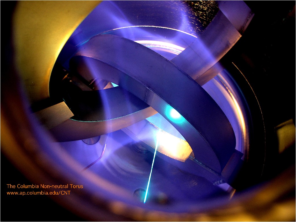
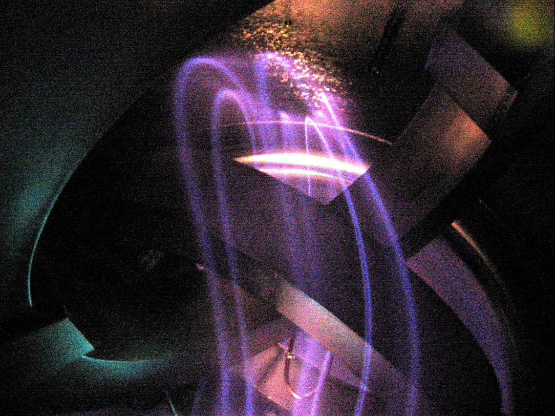
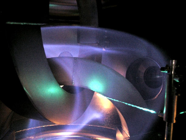
The above image shows a (neutral) nitrogen plasma created by a 200eV electron beam that travels along the magnetic field lines, visualizing the magnetic surfaces of CNT. The image is taken through a glass window at the top of the vacuum chamber.
First non-neutral plasmas:
Since spring of 2005, we have been doing experiments with non-neutral plasmas. First off, we confirmed that the CNT magnetic surfaces were filled with electrons. The electrons were emitted from a biased, heated tungsten filament, and were detected by measuring the potential on three other tungsten filaments, spaced 8 cm apart, each terminated to ground through a 1 Giga-Ohm resistor. Below is a potential profile for a -300 V bias.
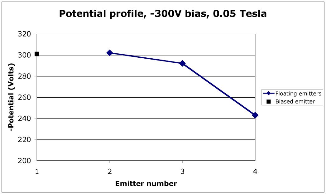
Our results show that the plasma density is on the order of 1012 m-3, and the electron temperature is about 4 eV near the center of CNT. Therefore, the Debye length is approximately 1.5 cm, much smaller than the averaged minor radius (~16 cm). This means that the plasma criterion is satisfied. These conclusions were by published in Physical Review Letters in 2006.
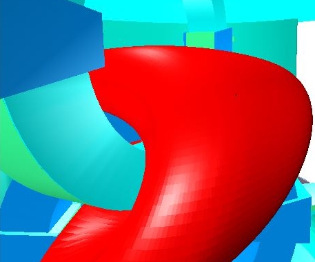
First field line mapping results:
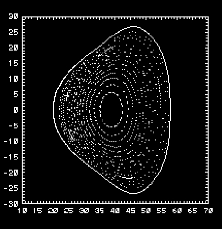
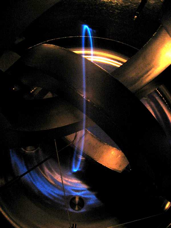
Left: Actual field lines mapped out at B=0.08 T with 50 eV electron beam and phosphorescent rod.
Right: Calculated drift surfaces for 50 eV electrons in reference configuration:
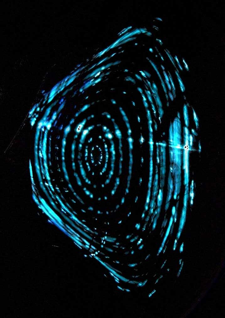
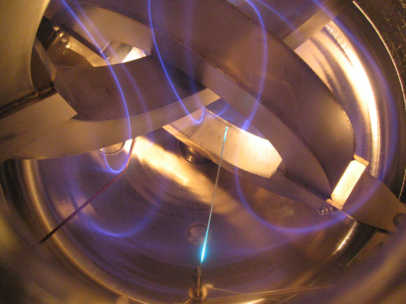
First light on November 12, 2004:
Air at 10-5 Torr is ionized by the electron gun, visualizing the magnetic field lines. On this picture, taken with a regular digital camera with an exposure time of 5 seconds, one can see the first six transits of the magnetic field line wrapping around its magnetic surface. A faint halo of emission from the rest of the magnetic surface is barely visible on this picture (it was clearly visible with the naked eye). A back of the envelope calculation confirms that the charged particle inventory was large enough to constitute a plasma - although not of the kind that will be studied in CNT.
Magnetic surfaces visualized (Jan.-Feb. 2005)
Magnetic axis (w. CAD drawing for comparison)
Internal surface, seen from the side (w. CAD drawing for comparison)
Surface near the edge, seen from above:
Experimental overview
Timeline of recent progress (since
June 2004):
2007: Further confinement and equilibrium studies. Studies of sudden
confinement jumps. Off axis injection of electrons.
2007: Detailed study of ion=related instability – frequency and amplitude
dependence on neutral pressure, magnetic field strength, bias voltage etc.
Late 2005-2006: Systematic investigation of equilibria and confinement in
CNT. It is determined that at low
neutral pressures, confinement is limited by the presence of insulated rods.
September 2005: Inspired by Prof Himura (visiting) experiments at elevated
neutral pressures were performed, confirming the existence of an ion-related
instability
June 2005: Temperature estimates confirm that the Debye length is small ñ the
electron clouds are plasmas
March-April 2005: First injection of low temperature electrons
January 2005: Detailed magnetic field line mapping at 64 degree tilt angle,
confirming large magnetic surfaces
November 12: First operation of CNT! Confirmation of magnetic surfaces.
Production of neutral plasma ionized by electron gun!
November 2: IL coils successfully installed in vacuum chamber
October 22: Preparations for IL coil installation begin
October 20: PF coils hooked up to cooling water and to electrical power.
October 18: IL coils arrive in CNT lab
October 11: IL coils complete - shipped from California
October 4: IL coil 2 passes helium leak check
September 28: IL coil 2 case welded and attached to pumps for leak checking.
September 22: IL coil 2 leads finished. Case tack welded on.
September 21: IL coil 2 wound; still needs to be encased
September 16: Winding of IL coil 2 begins
September 15: IL coil 1 vacuum pressure impregnated and complete
August 30: IL coil number 1 successfully helium leak checked
August 26: IL coil number 1 fully encased
August 20: Integration of vacuum chamber and PF coils complete
July 23: Vacuum chamber reaches design specification pressure of 2*10^-10 Torr
following bakeout to 140-200C
July 21: PF coils pass full electrical tests and preliminary water flow tests
July 6: Vacuum chamber reaches 5.7*10^-10 Torr pressure after a bakeout that
heated the chamber to 100-150C.
June 16: PF coils arrive
June 11: PF coil number 2 done
June 10: Vacuum chamber arrives
June 9: IL coil number 1 wound but awaiting vacuum jacket
June 1: PF coil number 1 done
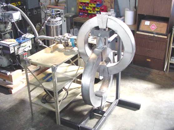
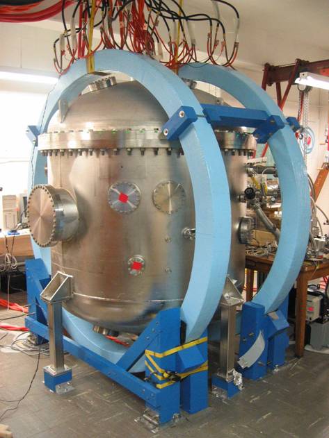
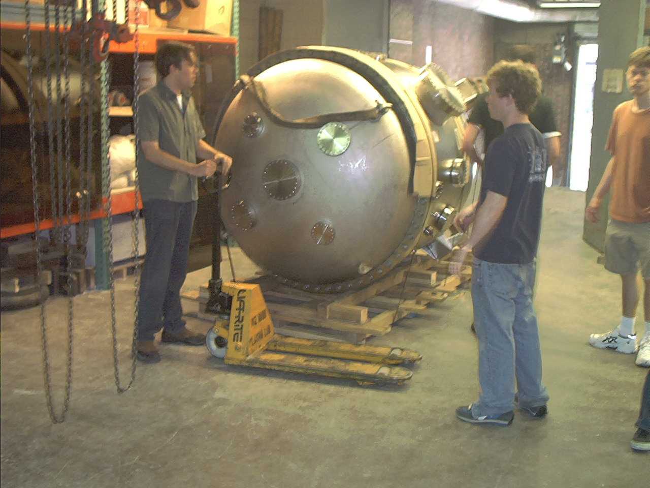
Vacuum chamber:
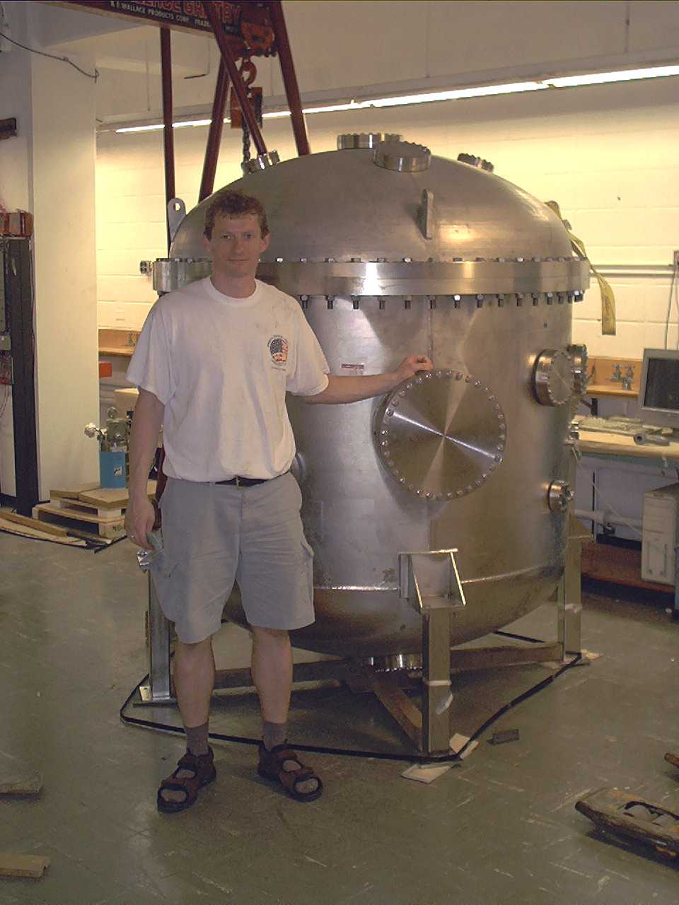
Vacuum chamber in the CNT lab
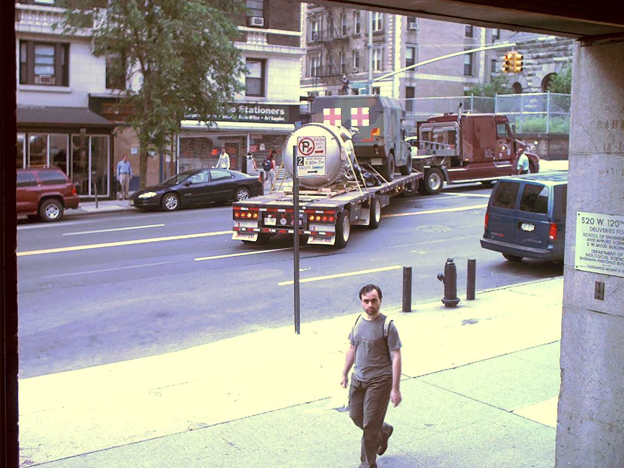
The vacuum chamber is cylindrical, in 316L stainless steel, with a height of 75 inches and a diameter of 60 inches. The chamber has reached 2*10-10 Torr - ultrahigh vacuum. The chamber was built at Ability Engineering in South Holland, IL. Below are some pictures of the arrival of the vessel..
Delivery truck backing into loading dock
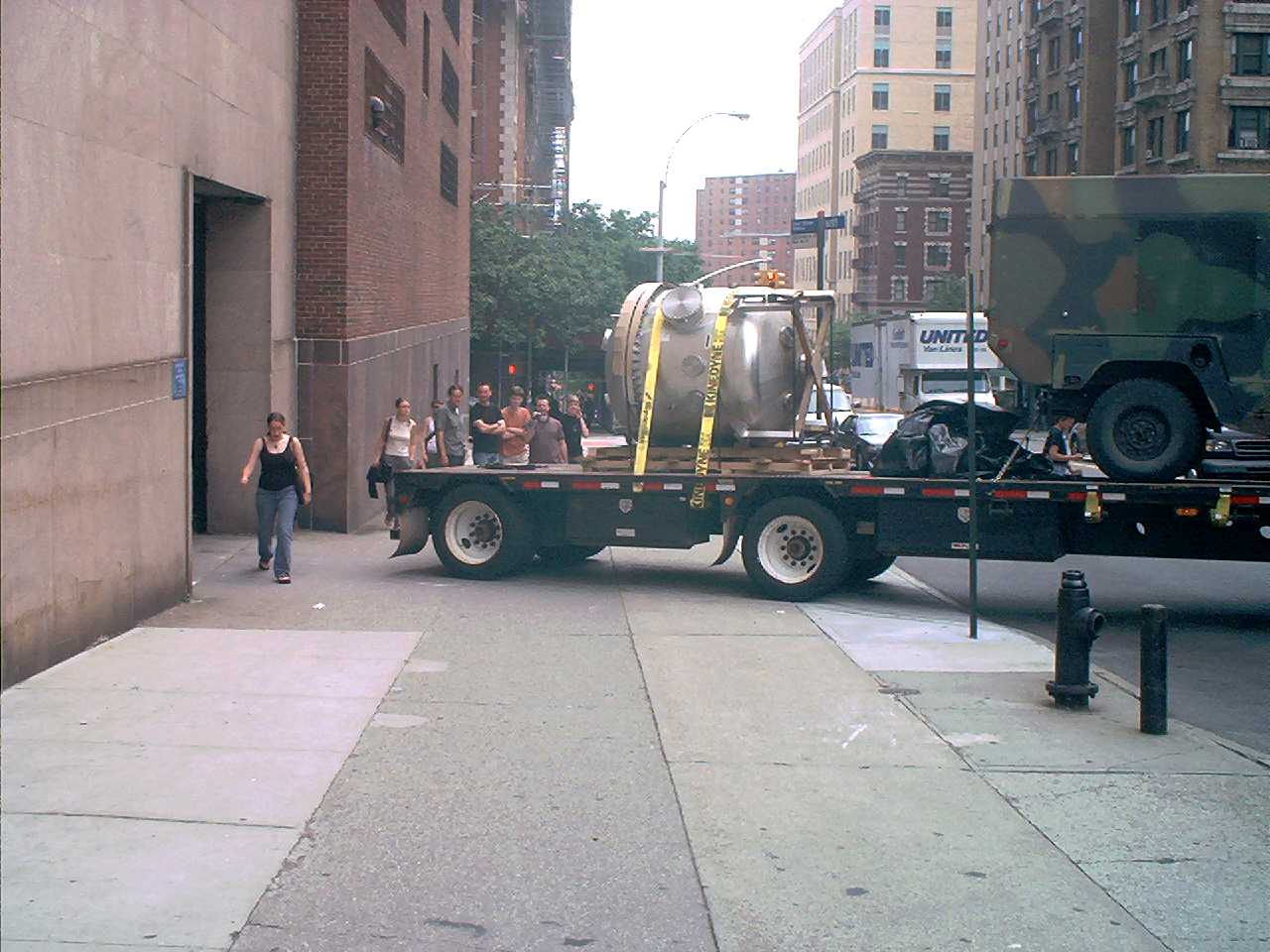
Inside Carleton Lab
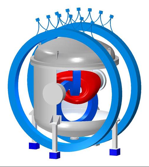
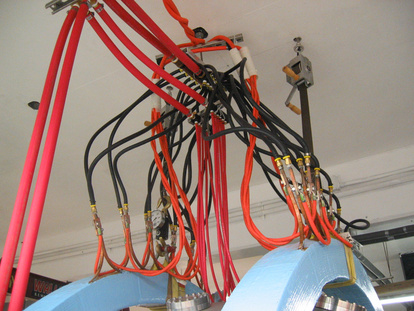
PF Coils:
As shown at the top of this page, the PF coils have been installed around the vacuum chamber. These coils were manufactured by AMP Electric Machines, a small startup coil manufacturer in Mertztown, PA. They were delivered in early June 2004, on time. Below is a picture of the water and electrical connections to the coils:
IL Coils:
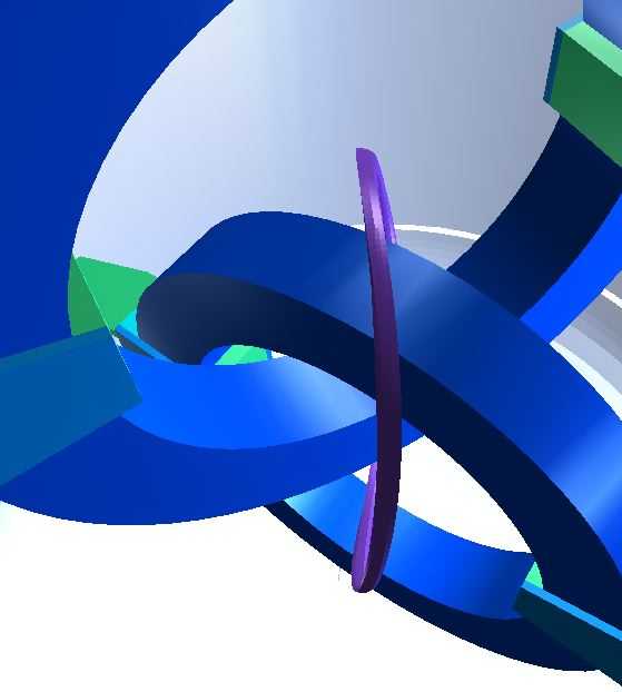
IL coils at 64 and 88 degrees with the coil fixtures shown
The entire stellarator configuration is created using only four circular coils. Two interlocking (IL) coils, are at the heart of the device, situated inside the vacuum chamber. The angle between the coils can be varied manually from 64o to 88o, allowing us to explore a variety of different magnetic configurations. The coils are powered from a 200 kW DC power supply. The IL coils were constructed by Alpha Magnetics, Hayward, CA.
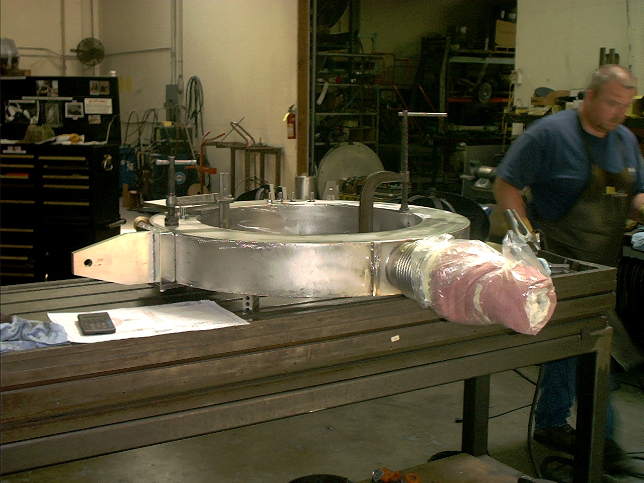
Side brackets being welded on
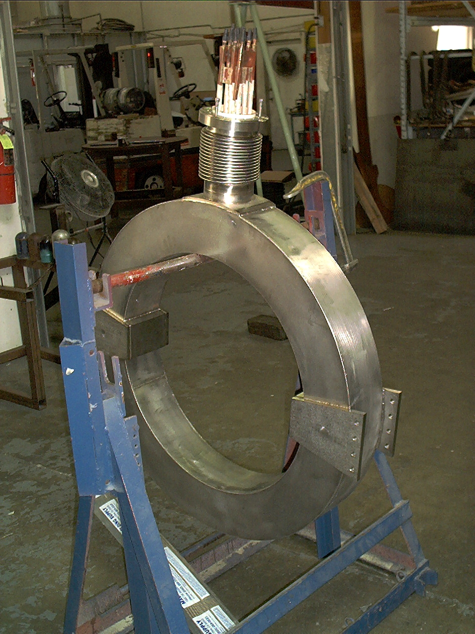
IL coil 1 in its vacuum chamber, ready for leak checking.
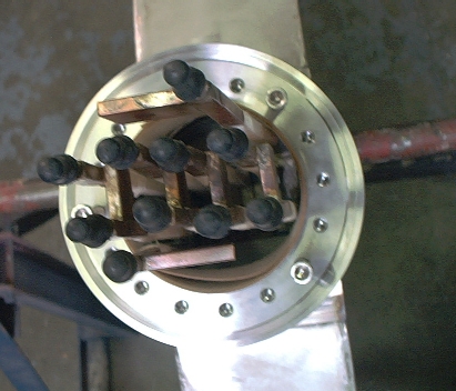
Leads coming out of custom 6.75 inch flange
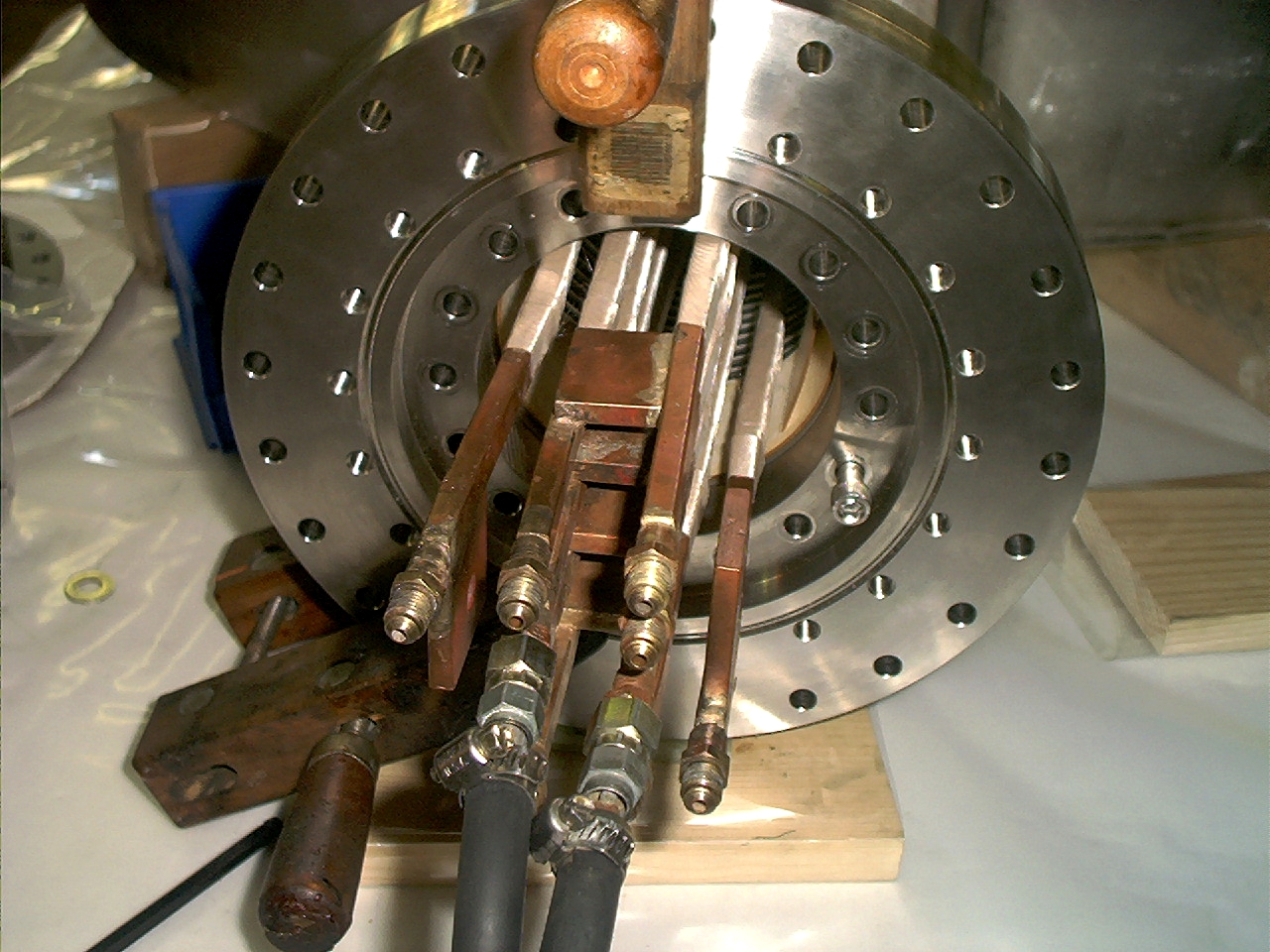
Leads sticking out of the flange assembly - similar to what it will look like at the top of the vacuum chamber.

Leak found at weld transition
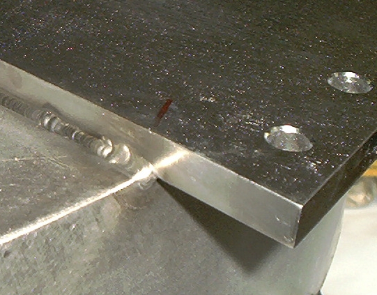
Leak fixed
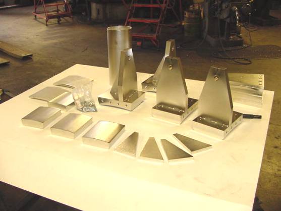
Various pieces of the coil brackets, annealed and electropolished
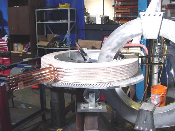
IL coil 2 wound interlocked with finished IL coil 1
All pancakes wound
Stainless steel can tack welded on
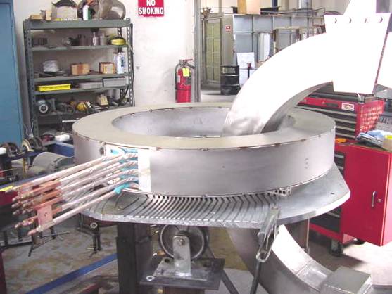
2nd coil ready for leak checking